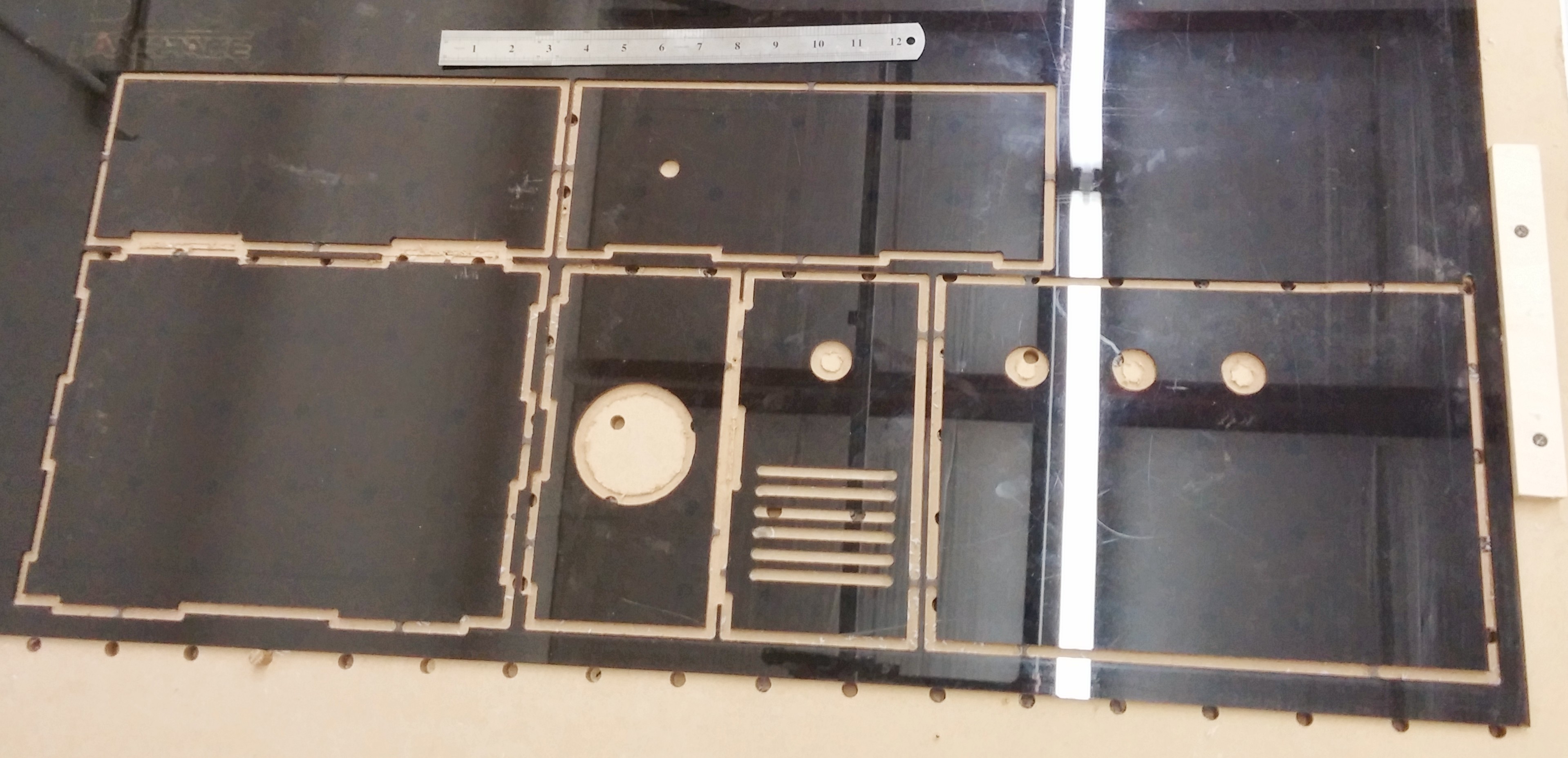
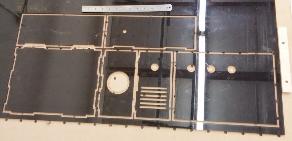
Using the CNC Router to make the electronics box for the CNC Router.
Design was done in Sketchup 2014 with interlocking tabs.
I used the SketchUCam plugin from Phlatscriptboyz to ready the design for the CNC Router. The SketchUCam plugin has two tool bars that work together. One is called PhlatBones that helps solves a common CNC problem. As you can see in my design I have square corners on all of my tabs for interlocking the box together. It is hard to cut a square corner with a round bit. SketchUCam PhlatBones script tools makes it easy to create the rounded corners so that all the pieces fit together nicely. It creates a small gap at each corner. If this is not acceptable then the corners may need to be cut out manually with a band saw.
The second tool bar is used for assigning all the cuts to the drawing. First thing is to configure SketchUCam to know what kind of bit I was using. In this case it was a 1/4″ bit, plus the speeds I wanted to use while cutting. I then started using the tools to assign cuts to my drawing. I used the “Insided Cut” tool for the circles. “Outside Cut” tool for the outside frame, and the “Centerline Cut” tool for the fan grill lines. The Sketchup “group” command can then be used to group certain cuts together based on user preference. The “Tab” tool was then used to add tabs to the outside lines so that the piece being worked did not move while being cut. The settings for the tabs was 3/8″ wide with 50% cut-through. You can see some of the tabs in the picture above. These were easy to snap off after cutting.
Next step was to generate the G-Code using the “Generate G-Code” green arrow tool. This runs the script to generate the G-Code and then displays the cuts visually with a built in viewer. This is inspected to see if G-Code is doing what the user intended.
I copied the G-Code cnc file over to the CNC Router and after setting the zero point of the router, started the router cutting. I used the shop vac to vacuum the acrylic bits and to hold the material down. Two more projects for the CNC router is a vacuum shoe and a vacuum table.
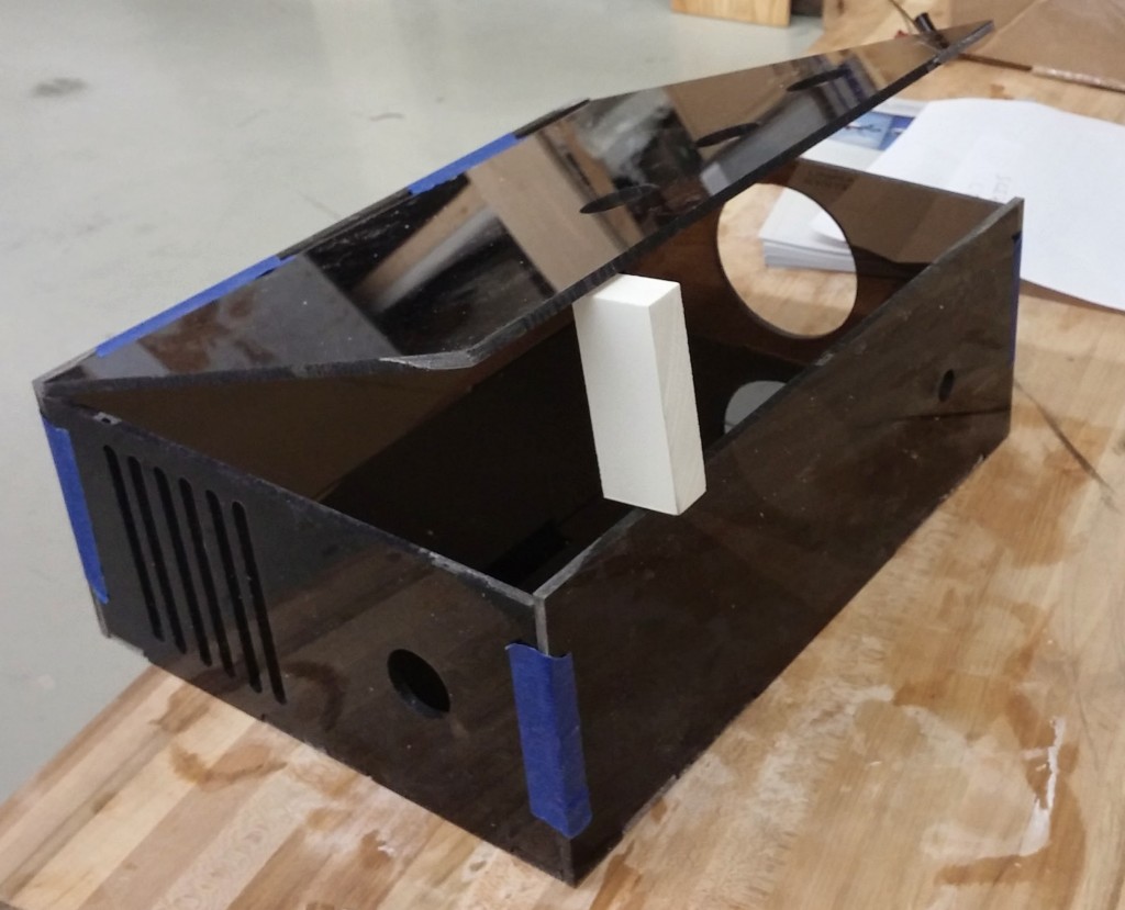
I snapped the pieces out of the big acrylic sheet and sanded the tabs flush with the edges. I temporarily taped the box together to see what it looked like and how well if fit together. I have a few holes that I have to drill before I put it together. I still need to work out how to change bits in the middle of the cut.
Part of building the CNC electronics box is to add 3 new control buttons and the Emergency Stop switch that should make operating the CNC router easier. I plan to have a class on the CNC router at that time that should be in the near future.


