
ARM Pro Mini Board Layout
ARM Pro Mini Before Reflow
I decided to try my hand at making a simple ARM Cortex microcontroller board. I based my board on the ARM Pro Mini design. The ARM Pro Mini uses an NXP ARM Cortex M0 chip, and has the nice feature of letting you drag and drop program files on to the chip as a USB mass storage device.
I essentially copied the existing ARM Pro Mini schematic in KiCAD and then started making my own modified board layout. I ended up with a design that I could panelize to fit 8 copies on a SeeedStudio 10cm x 10cm board.
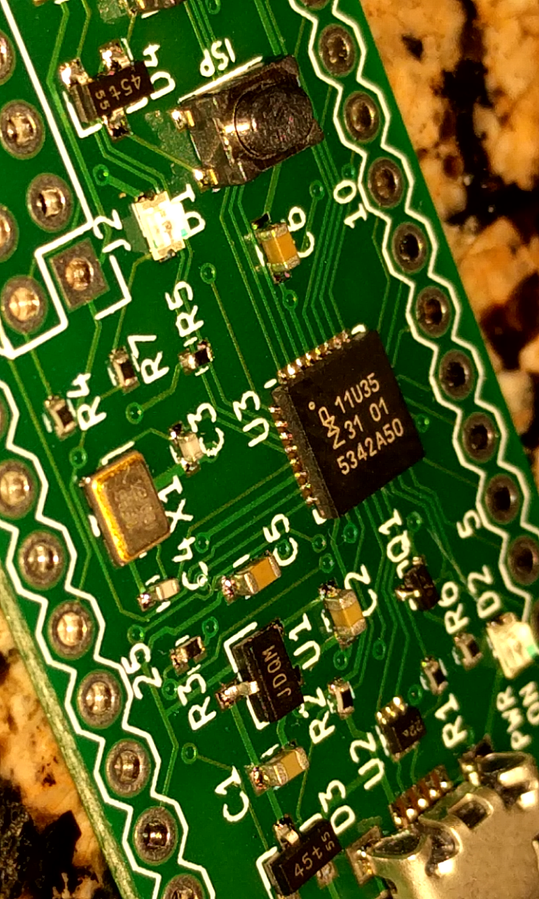
I ordered a set of boards from SeeedStudio, and got a laser cut solder paste stencil from OSH Stencils. I have reflowed a number of boards by just hand applying solder paste, but this design is the first I have attempted to use tiny 0402 sized resistors, and it has a tiny 32 pin QFN chip for the ARM processor. I pasted a board and got to work placing all of the components with tweezers. Time for the moment of truth! I put the populated board in the toaster oven and watched as the solder paste melted into nice shiny solder joints.
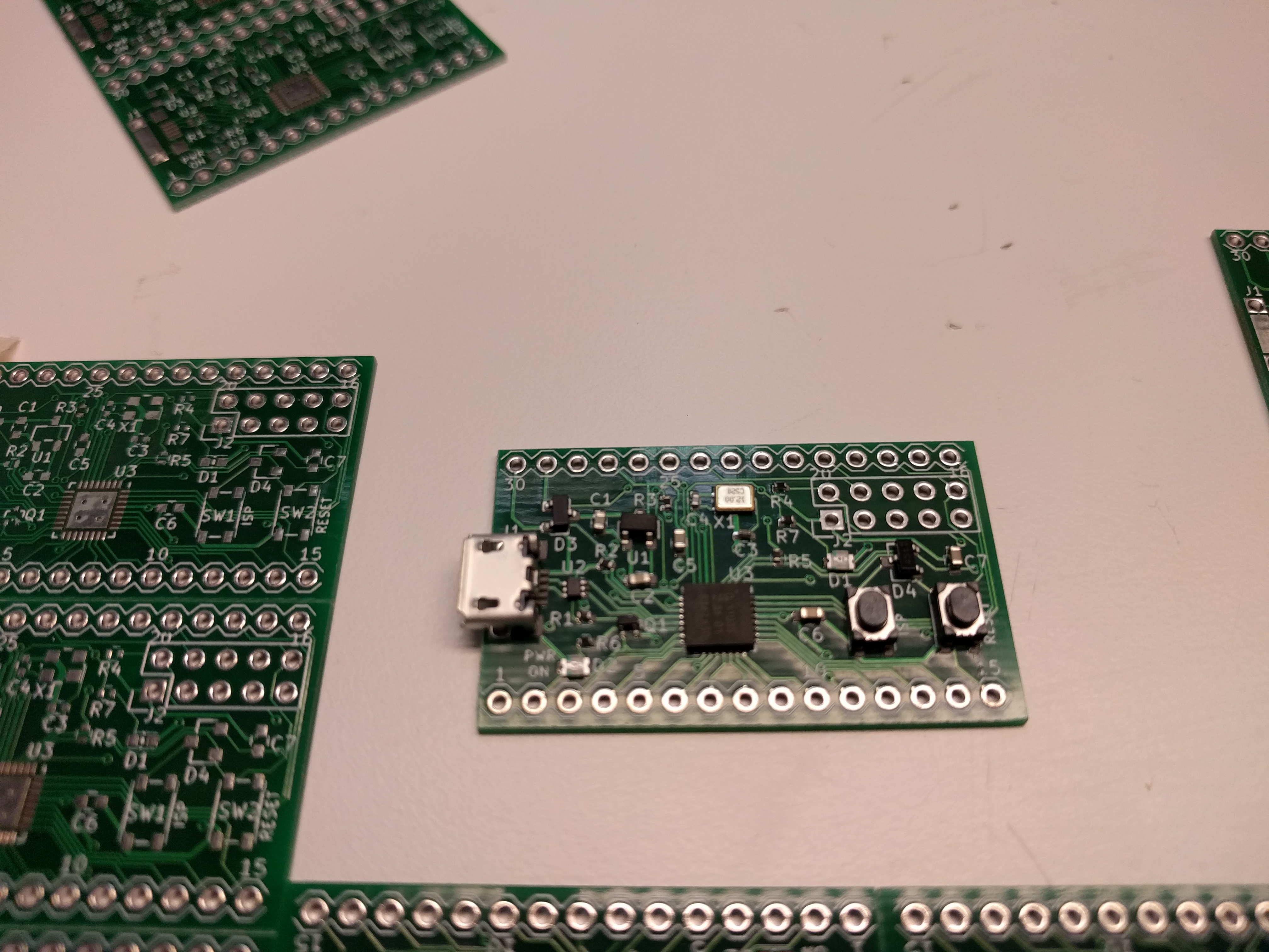
The board out of the oven looked really good.
Soldered Board
I connected a USB cable and plugged the finished board into a computer. Initial signs were good. The power LED lit up, so at least the basic power input was good. Unfortunately, there was no sign of any actual USB device showing up in the operating system. I spent a bit of time troubleshooting the board. I first measured the DC power input voltages at all the pins they should be. I also checked for continuity between various pins to make sure that there were no short circuits between pins on any of the tiny surface mount chips. Everything seemed to be OK, so I spent some time reviewing my circuit design for errors. I double checked the schematic against the original ARM Pro Mini design and ruled out problems there.
Eureka!
While double checking some pinouts in data sheets, I found the problem… According to the datasheet of the pushbutton switches that I used on the board, the two terminals on each long side of the switch are tied together. I had unfortunately drawn the terminal layout in KiCAD rotated 90 degrees, tying the two terminals on each short edge of the switch together. This effectively makes my switches always “pushed” on my board.
PRO TIP:If you generally use any two opposite corners of most pushbutton switches, you can avoid this problem
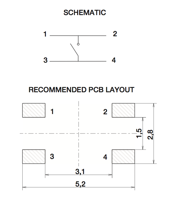
Switch Pinout
How to Fix What You Screw Up
I sat around for a minute annoyed that I have a bunch of boards that won’t work. Then I started to brainstorm ideas for work arounds. I initially thought about some kind of intermediate adapter layer between the board and my switches. Then I came up with an alternate idea. What If I could rotate the switches and solder them on crooked?
I played around with rotating the switch footprint in KiCAD.
Looks like it should work!
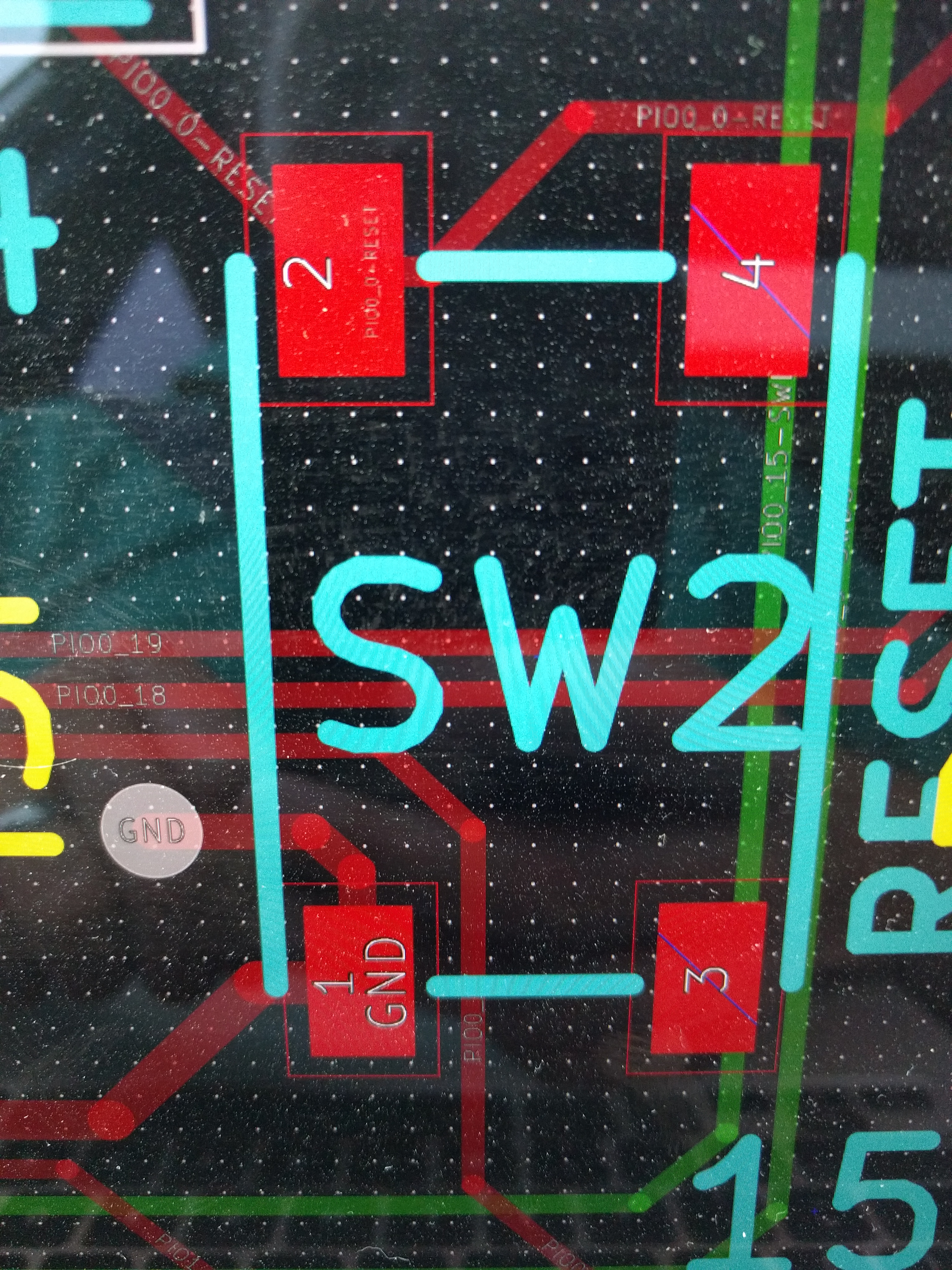
Original Switch Layout
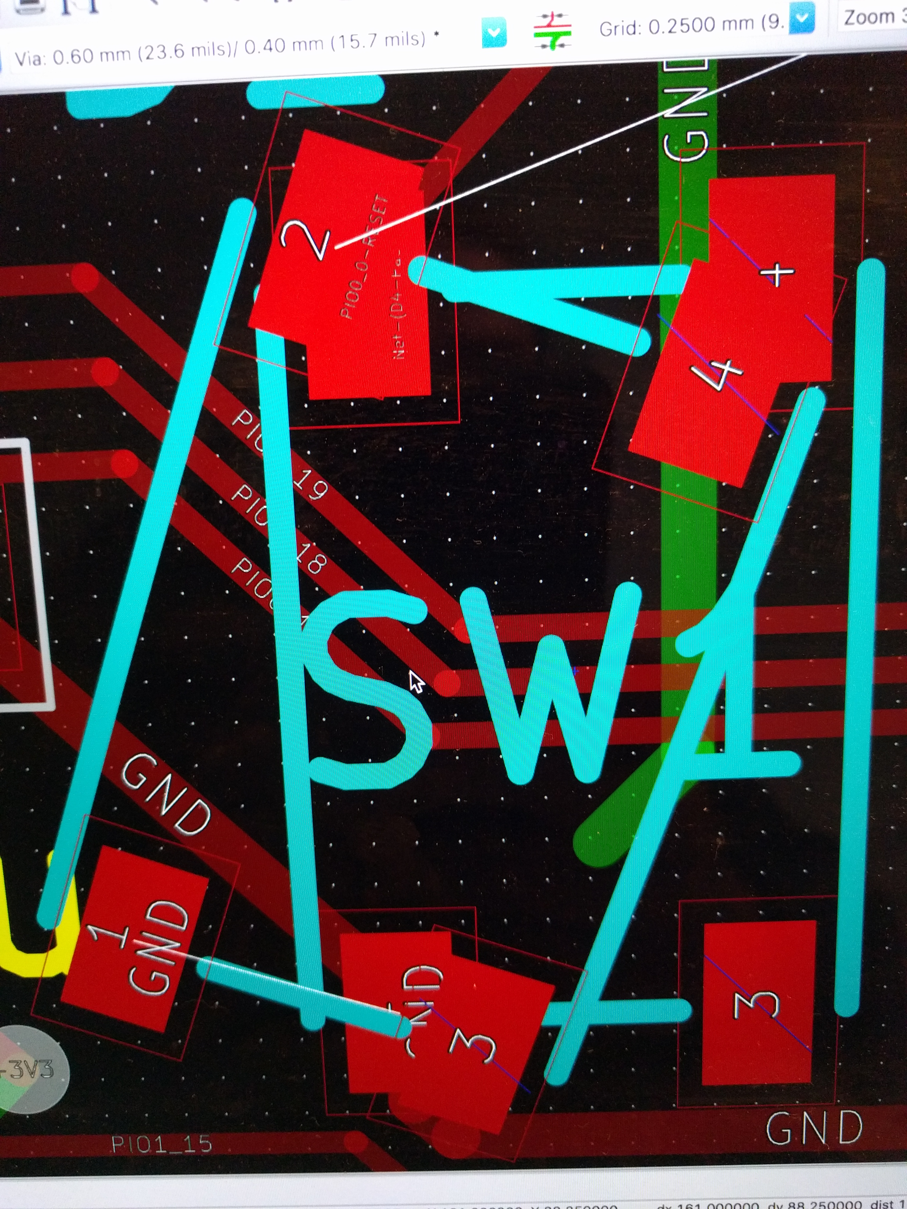
Hacked switch layout
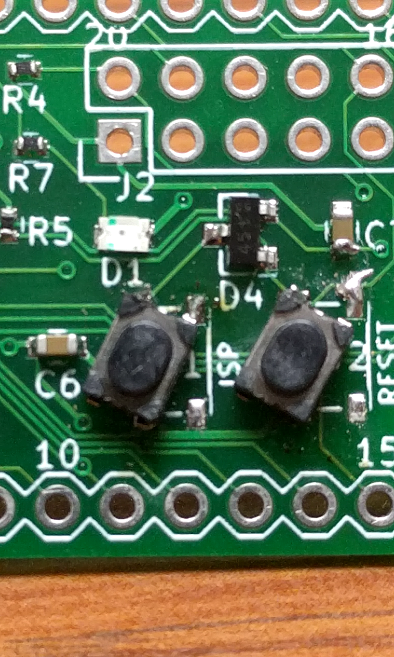
I tried to unsolder the switches on my board, but melted them in the process. I got some fresh switches and did an ugly hand solder job to attempt to replace them in the new, slightly tilted orientation.

Switch hack
I gave the new fix a shot by plugging it in to my computer. Success! The board showed up as a new mass storage device and some quick test programs worked just fine.