Our current CNC router is controlled by an Arduino Uno board with a perfboard shield on top that breaks out the connections to the motor drivers and limit switches. The perfboard solution was hacked together quickly to get the router up and running. One of our goals is to clean up the wiring and install it in a more permanent enclosure to help with maintenance, reliability, and electromagnetic interference issues.
To clean up the Arduino and perfboard piece, I made a new control board. The board is essentially an Arduino Uno clone, based on the Arduino Uno rev3 schematic.
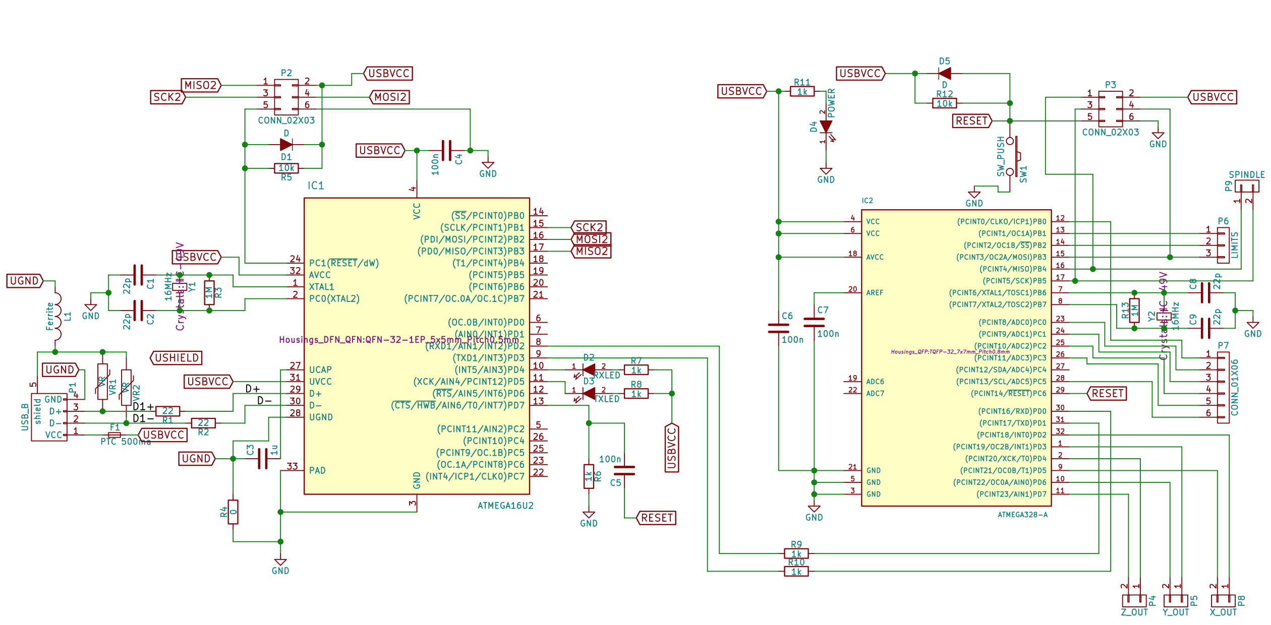
Board Design
I drew up a schematic in KiCAD that copies most of the Arduino Uno circuitry, but ommitted the DC power input subsystem, since we can power the board via USB from the router’s touchscreen computer. I used a surface mount ATMEGA 328 chip instead of the DIP packaged ATMEGA 328p that is on standard Uno boards. I connected the pins of the ATMEGA chip which are used by the Grbl control software to pin headers on the board.
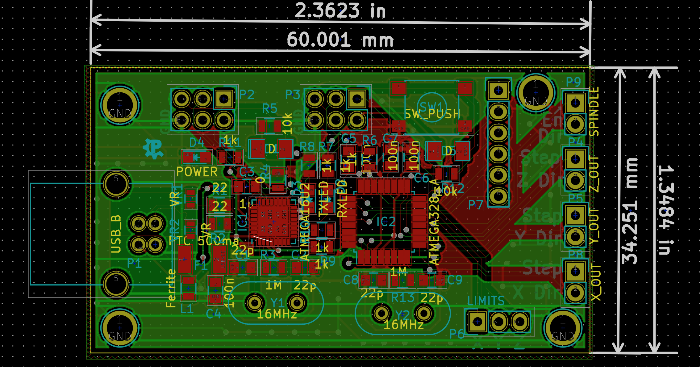
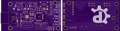
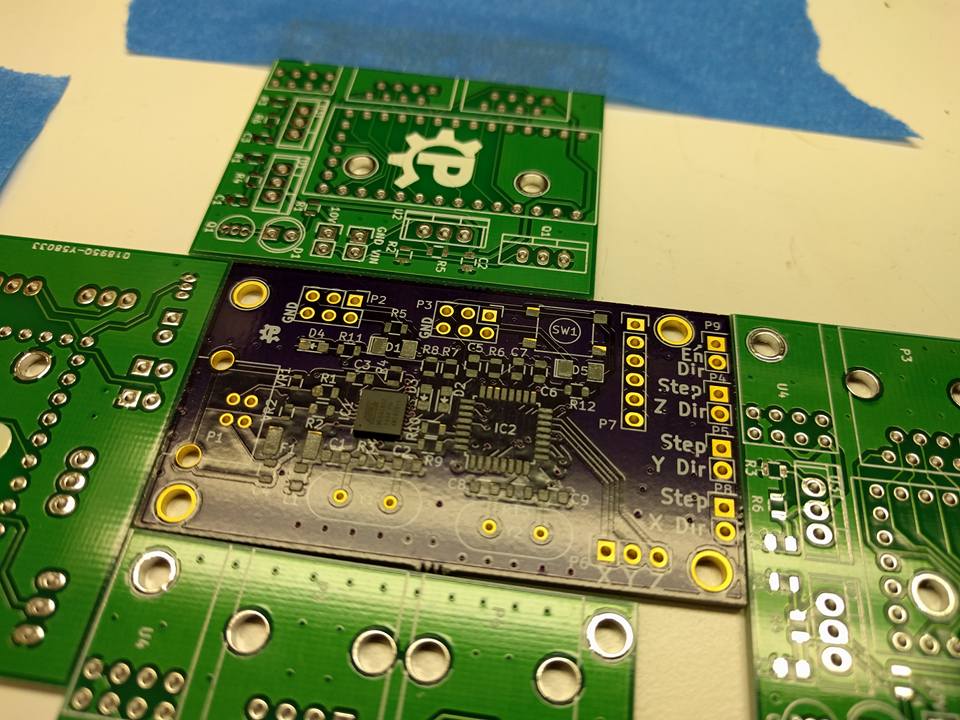
I used KiCAD to lay out the PCB, ending up with a roughly 2.4in x 1.4in 2 layer board. I added some obligatory PaxSpace logos to the silkscreen and sent the board off to OSH Park to get a few boards manufactured.
Board Assembly
I was contemplating applying solderpaste to the pads by hand using a toothpick or similar device. After I got the boards in the mail, I had a change of heart due to the teeny tiny size of the pads for the ATMEGA 16U2 USB bridge chip. I broke down and ordered a solderpaste stencil from OSH Stencils.
The stencil worked out great! I stenciled some paste onto the pads and placed all of the surface mount components carefully on the pads with tweezers. I stuck the poulated board into the reflow toaster oven at PaxSpace and watched the paste melt, soldering the components nicely in place. After reflowing the surface mount parts, I hand soldered the USB connector, the crystals, and the pin headers.
Solder paste and placing components
Board after baking in the toaster oven
Oops
While I was placing the components on the board I realized that I had messed up the silkscreen labels on the bottom left of the board, swapping the ferrite bead and a capacitor. Luckily I caught the error somehow and put the components in the correct spots.
Somehow when I ordered the components for the board, I neglected to add 22 Ohm resistors to my order. These are needed for the USB lines on the chip. I ended up ordering some after reflowing the rest of the components and soldered them on by hand with a soldering iron.
Turning it on
Everything looked good after the initial assembly. I knew it wouldn’t work completely until I added those 22 Ohm resistors, but what the heck… I plugged it in and at least got the power LED to light up!
Oops again
I got the 22 Ohm resistors a week or so later and soldered those on. Then I tried to hook it up to a computer to start loading the firmware and Arduino bootloader on the chips. I started having weird intermittent problems with the USB connection. I noticed that the problems went away if I poked at the 22 Ohm resistors on the USB data lines. I went back and touched up my (terrible) hand soldering job on the new resistors and everything started working much better.
Next up, Grbl
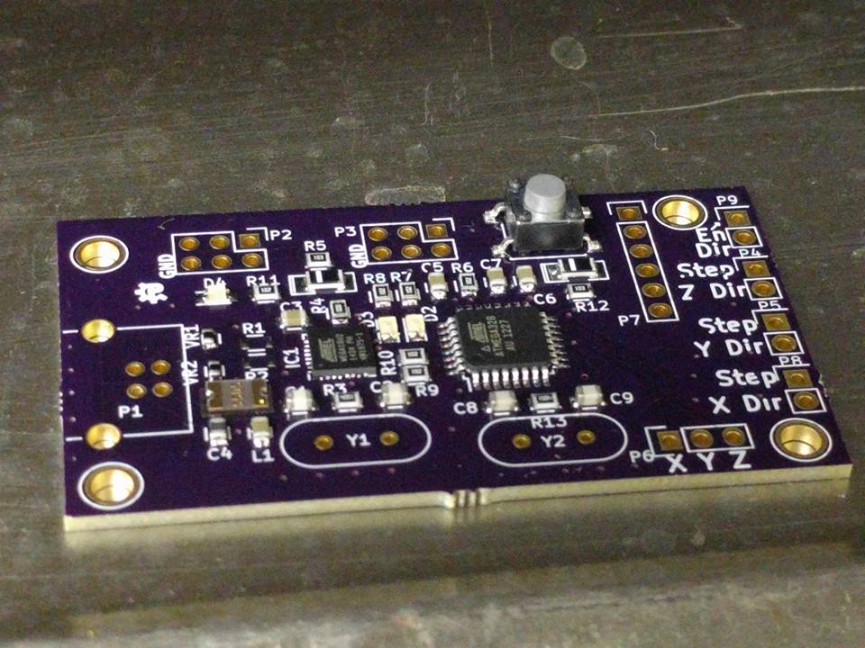
I was able to get the Arduino bootloader set up on the 328 chip and can successfully upload Arduino sketches to the board. Next we can upload the Grbl CNC control software to the board and start testing it with some stepper motor drivers and limit switches.

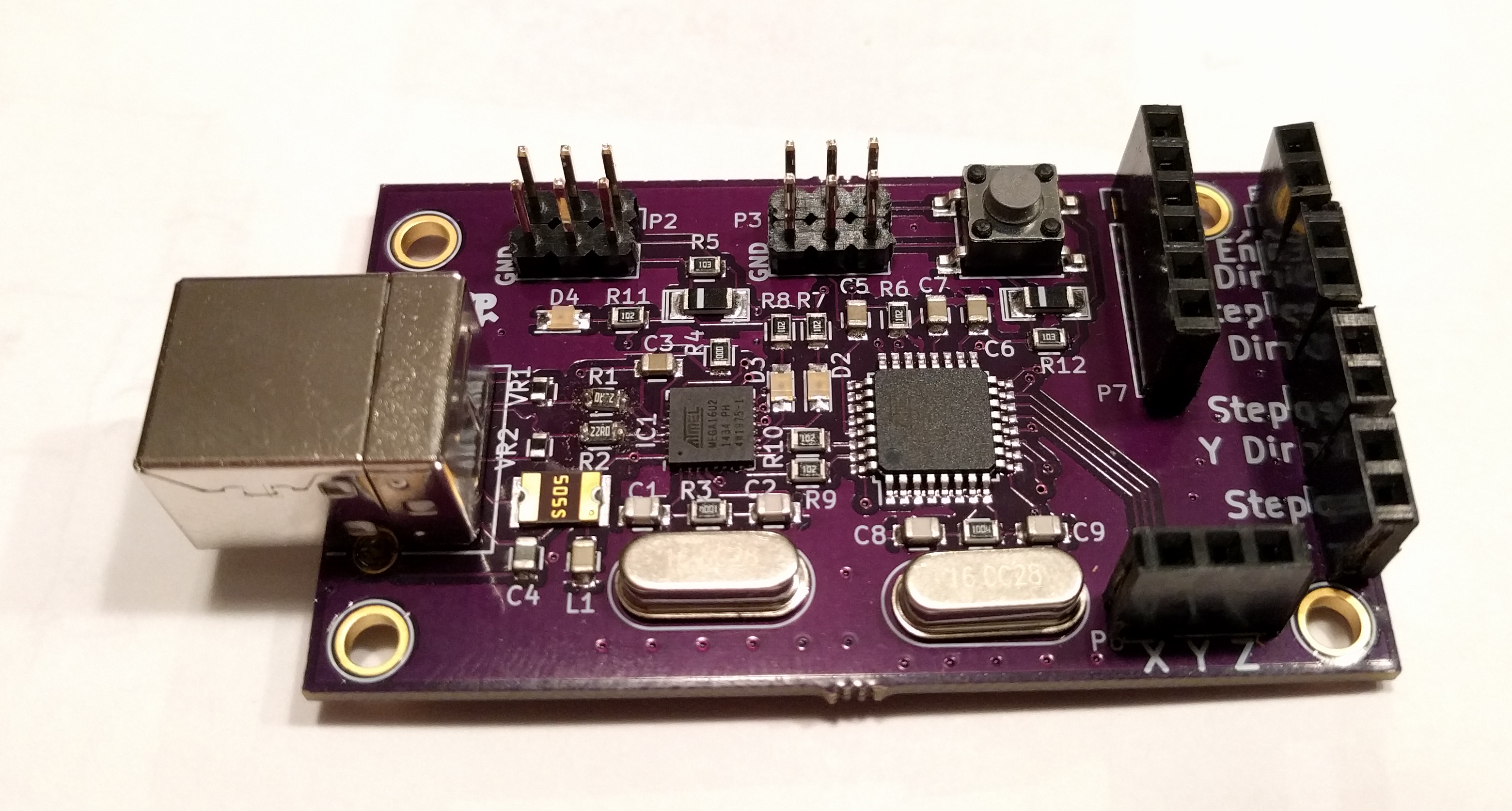
Completed board